Nixie Clocks, Take Two!
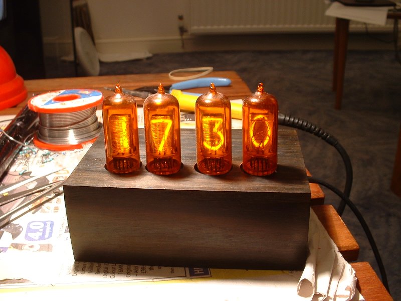
In a perfect world, this would be photographed against a carefully chosen background with two or three lights and reflectors to get the look just so... This ain't a perfect world, so what you see is how it looked on my work-table.
This is a further evolution of the clock whose history is described here...
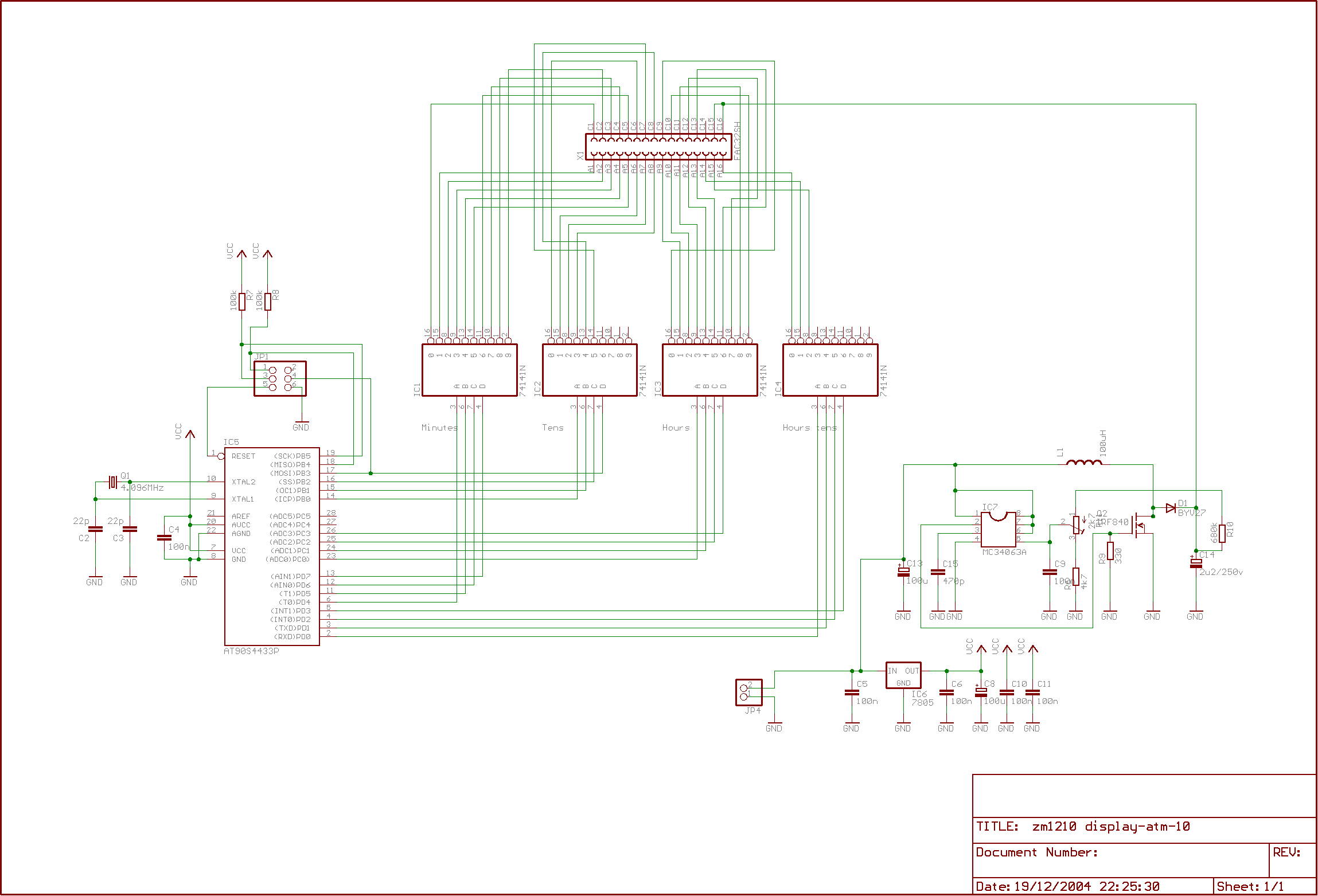
I won't repeat the stuff about the design, pausing only to note the gory details:
-
The clock is constructed on two boards; one carries the HT generator and the processor logic, the other the tubes. This allows a slightly more compact design that the previous effort, but didn't save as much real estate as I'd hoped.
-
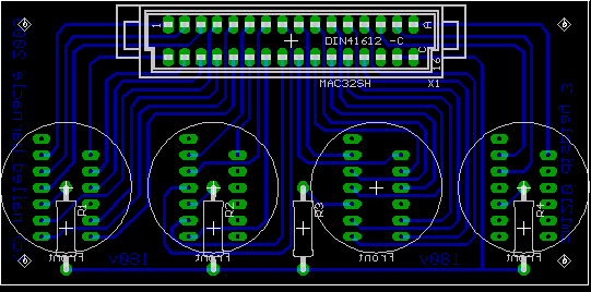
The tubes are mounted on a DIP 0.3" grid. This isn't ideal, but it has the advantage that the tube legs are diagonally braced and are far enough separated that tracks can be run between the lands. The bad news is that if the tubes are placed nearer than half an inch or so to the board, there is excessive stress on the leads which might have adverse effects on the seal.
-
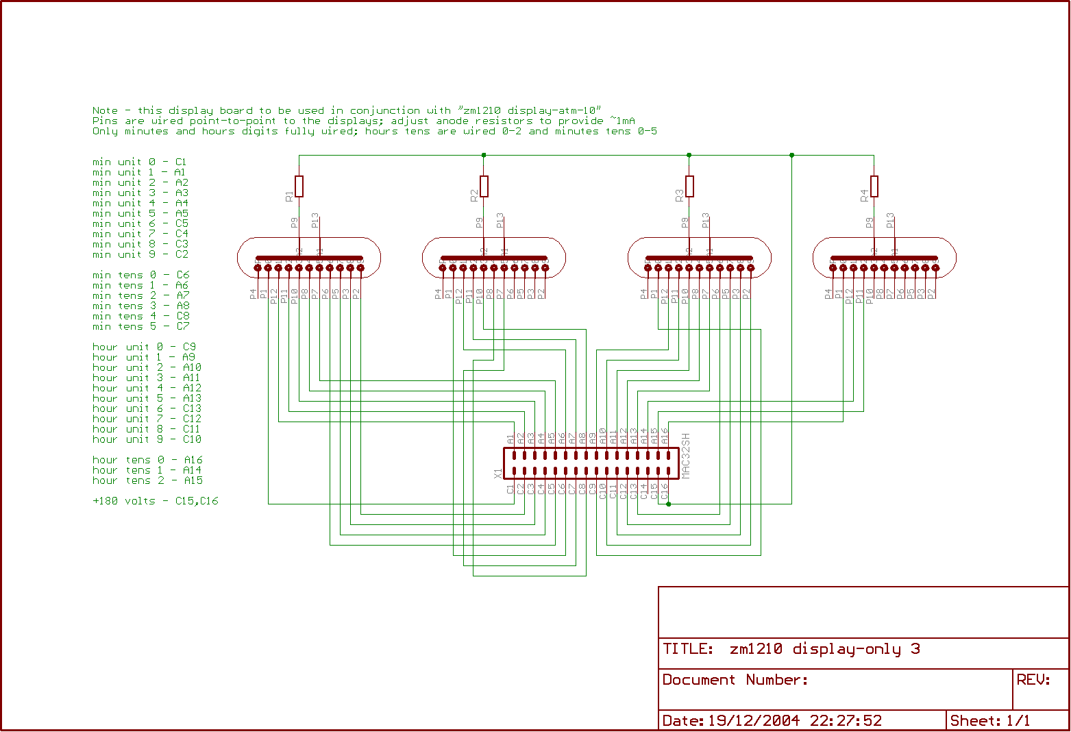
There are a couple of errors on the circuit diagram (below): the crystal is 8MHz not 4.096MHz and the processor is an Atmel ATMega8.
-
The box is cut from recycled ebony. 3mm thick sheets were cut from a block and glued together to create the shape; it was sanded on a belt and then by hand for the smooth surface, which was then polished using Danish oil and elbow grease. The holes were drilled before glueing but after cutting. The reason they're a little off-centre isn't a problem with the circuit board; I used recycled nixies too and the legs were a little bent before I soldered them in, and the holes are cut to fit.
-
There are no particular efforts taken to regulate the crystal, but in service in the case, it's been gaining a second a week. Near enough for me, I think; it's usually closer to the real time than another mains-regulated nixie clock I also have.
-
I don't like mains on circuit boards, particularly when - as here - there might be a risk of exposed mains in the case of a breakage, and there wasn't room for an isolating transformer, so instead the clock is powered through a surplus laptop power supply, providing a regulated 15v at up to 2A. I haven't measured the current, but as an estimate - 1mA each at 180v for the tubes; say 50% conversion efficiency gives about 1.5W for the display, and maybe 200mW for the driver logic.
-
The time is set using the two switches which share the programming connector. One switch cycles between a normal display, a display where only the hours are visible, and one when only the minutes are visible. The other advances the selected time one hour or minute forward per click.
-
The time fades smoothly as the digits change.
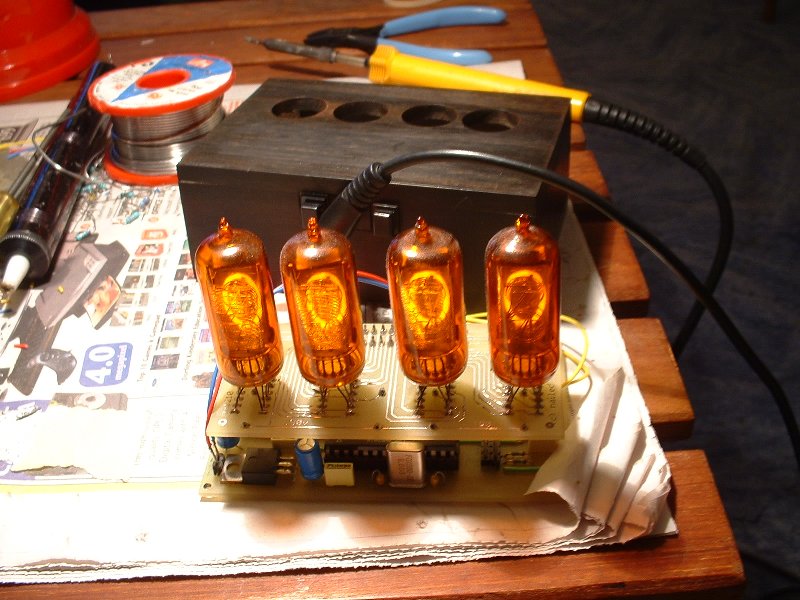
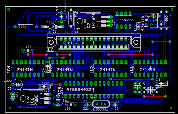
You'll see that the circuit board for the display has the tracks uppermost. It's impossible to solder the connector on a single sided board otherwise. Both boards are single sided, though the controller board has half a dozen wire links which I've shown on the layouts as top-side tracks.