Why?
Any car has faults - ranging from poor running to complete failure - and many of those relating to the Fiat Coupe are down to faulty sensors.
There is an indicator light, but it's not always that useful - for one thing, the only official way to tell what it means involves plugging an expensive tester into the car, an activity for which Fiat main dealers will cheerfully relieve you of large sums of money.
This page documents my device to maintain communication with the ECU.
This has two advantages: it allows you to display engine parameters in real time - showing any two, three, or four of the dozen or so parameters available; and it shows up to three sensor errors (including supplementary information, when available).
What?
I've designed a small system which uses the same diagnostic connections as an official ACR. An LCD graphical display shows the data in text and graphical form; it is also possible to set up the device and log real-time data on a laptop computer using a serial link.
At the moment, the device can only speak to the Fiat Coupe 16V NA or 16VT, or its close relatives (some Lancias and Alfas). The next stage will produce code to handle the 20V and 20VT.
Some pictures...
Showing the PC connector
And the engine and power leads
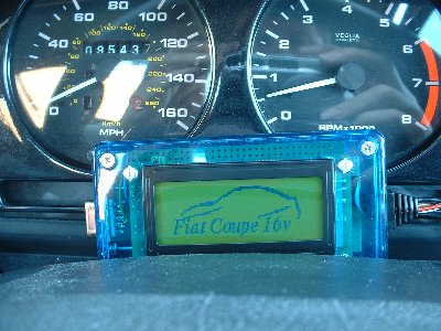
Initialising, in a temporary position on the dashboard. The logo is that of the Fiat Coupe Club UK and is used with their permission. Fiat Coupe Club UK neither endorses, guarantees, or recommends this device, and are in no way associated with it.
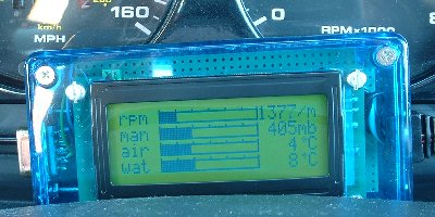
Close up of the display in operation.
Update 2008
Since this page was written, I've run several iterations of the design. This is the Mk IV - functionally identical to the original but using a display with improved resolution and in a mounting plate made by Hansell Composites Limited - who were incredibly helpful, speedy, and generally all-round nice guys. Also, given that serial ports are now something of a dying art, it uses USB to communicate with a host computer.
The data below still refers to my original design (I don't want to give *all* my secrets away!) and which is further documented on Steve Ciarcia's Circuit Cellar.
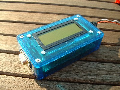
Some pictures...
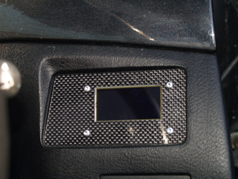
With the display off.
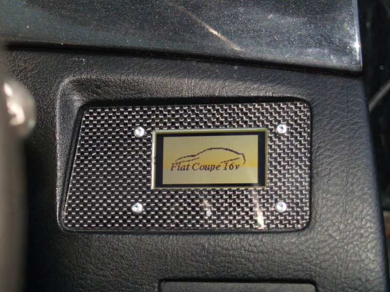
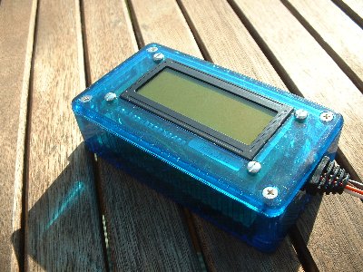
Initialising.
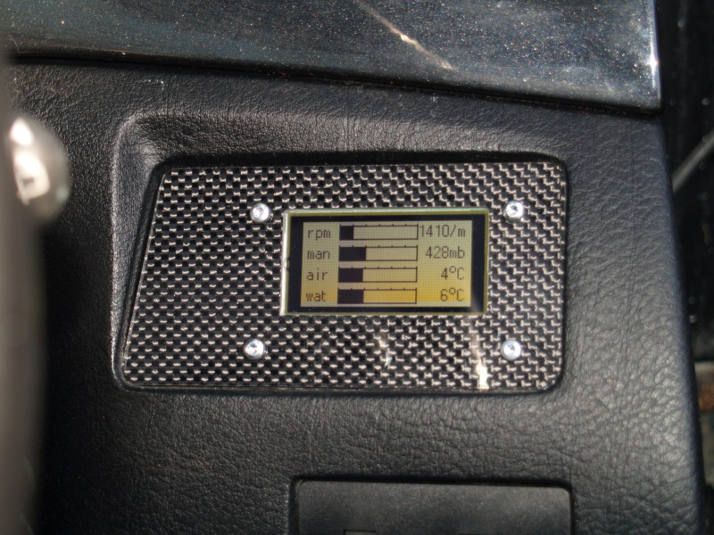
And in operation.
The circuit
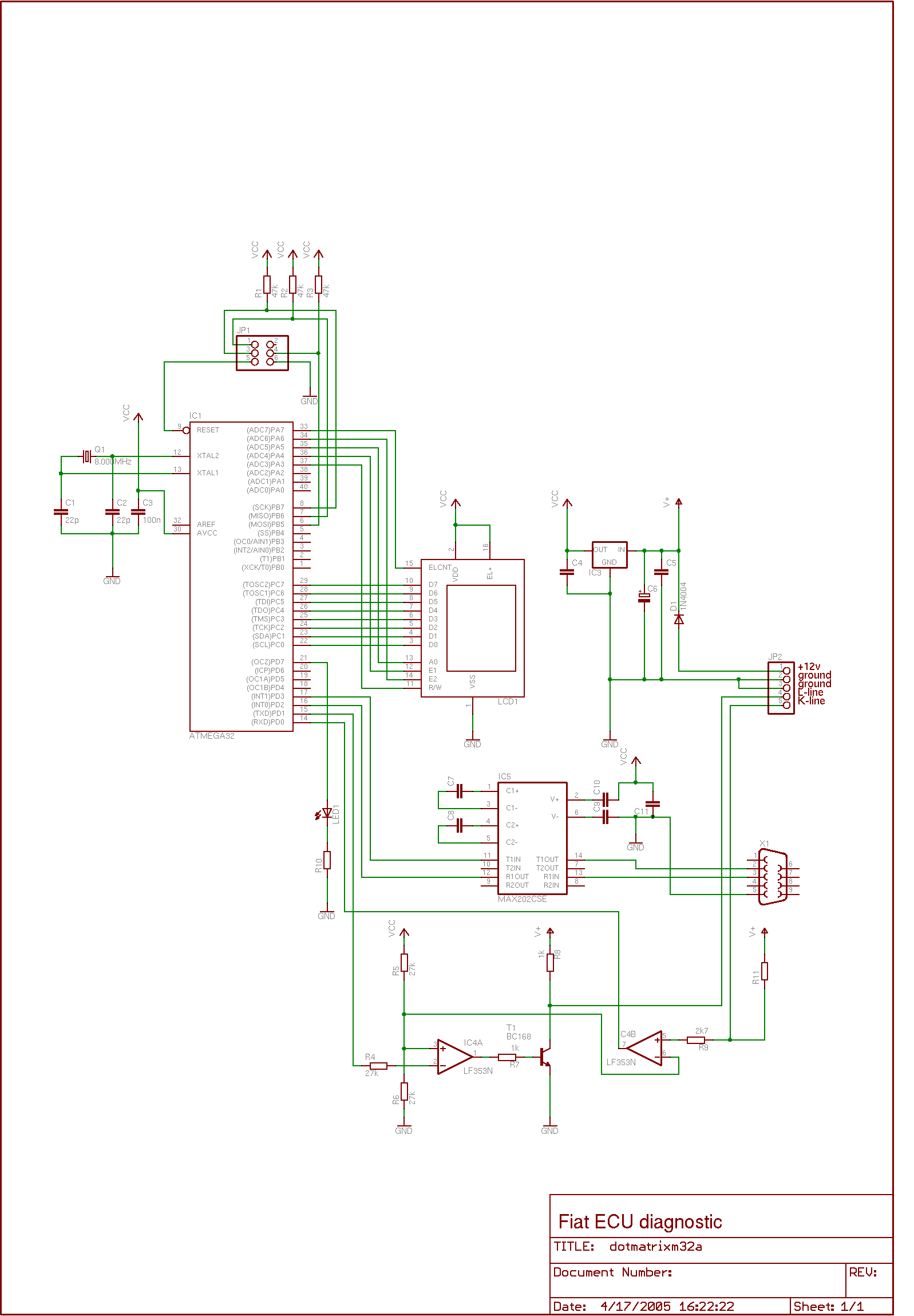
The circuit is fairly straight forward. Because of the amount of data that needs processing, and for the graphical and text requirements, an Atmel Mega32 forms the central part of the system. The majority of the ports are used to control the display - a VK5121 LCD display with ELCD backlighting (generated on board). The VK5121 is capable of a 120 by 32 pixel graphics display, but contains no character generator so this has to be done by the Atmel.
IC5 converts the TTL data output from the Atmel to RS232 levels; IC4 (incorrectly shown as LF353N, should be LM358N) and T1 convert from TTL to ISO914 as used on the majority of cars (all cars which comply with the OBDII standards). The K and L lines are separated for use with the 16v cars, for the 20v cars which use a single K line for bidirectional communication, R11 (1k) should be removed and the two lines connected together.
IC3 and its associated diode and capacitors provide isolation from the electrical noise of the engine supply.
A programming socket is provided so that the code can be updated without removing the processor.
One thing to observe is that the Mega32 provides only a single hardware UART. This is used to speak to the engine; a software uart is implemented to maintain a 2400 baud serial comms line to an optional laptop computer.
Schematic drawing
Read the FAQ here