This page is intended to demonstrate the design of a reasonably complex nixie clock. I'll update it as I go along. I'll also be including PCB layouts, circuit diagrams, and software: all three aspects are free for use by anyone for personal purposes only. If you wish to make this clock for sale, please contact me to discuss terms.
Any information presented here is offered solely at the user's risk. Please note that dangerous voltages are present on the circuit board. If you make this clock and it (or your dog) bites you, or it doesn't work, or you just have a generally bad day, tough. It's not my fault.
For the record, I'm based in the UK so suppliers are also mostly UK based.
Nixie tubes require voltages on the order of 140v and a current on the order of 1-5 mA to strike. A common technique is to use mains voltage either directly or via an isolating transformer. This has the advantage of making a very (long term) stable 50 or 60Hz signal available to be used as a timebase, which gives a very good long term accuracy. On the other hand, it is either potentially lethal (requiring careful insulation for safety) or requires bulky isolating transformers. On the gripping hand, it requires hardware links to select between different mains voltages, and hardware or software links to select the timebase.
Small switch-mode power supplies are easily and cheaply available which can deal with world-wide supply voltages and frequencies. The major disadvantages are two: the timebase has been completely removed; and the drive voltage must be generated from the low-voltage supply. However, the biggest advantage is that of safety. Although there is still a need for dangerously high voltages, this voltage is now completely isolated from ground, reducing the chance of dangerous electric shocks.
Take your pick: there are at least six basic technologies that can be used to drive nixie tubes and provide the necessary logic. I have seen examples of at least four of them; it's quite likely that someone, somewhere has built clocks using all of them. In no particular order:
These days, microprocessors or microcontrollers offer the maximum flexibility of display. It is difficult to change the way a discrete logic circuit works; modern microcontrollers (e.g. pic, atmel) allow programming with simple and cheap (or free) tools while in circuit.
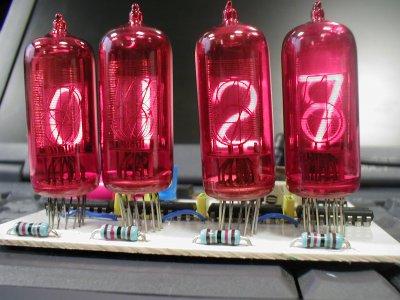
Again, there are nixie clocks out there with huge numbers of tubes and clocks with just one... My preference is for four tubes, normally showing hours and minutes. I also want to find a way of displaying temperature without any user intervention and in a way which is not confusing. To do this I propose to fade between the time and the temperature on a cyclic basis.
My clock will have:
It will fit on a small pcb (80mm by 100mm) which will be easy to make, and the tubes will be mounted on the pcb.
These have been very useful to me. Enjoy...
Some of the stages in the design process. Note - none of these have been tested. Use at your own risk... all designs use the Eagle PCB design software. To save space, the pcb layouts and designs are compressed using bzip2. Most of the schematics
The first version after the decision to go for a microcontroller. The power supply is an external 18v switch-mode, from an ancient laptop. The HT is generated by switching the input voltage through an 18:240v transformer, not shown on the diagram but connected at JP2 and JP3. This is driven directly from the processor, so if the processor dies there's a possibility of melting stuff. Not good. Plus, the external transformer isn't large but it's not as elegant as I'd like; the power transistors and regulators hang off the board, and the board has to be double sided - though almost all the links between sides are at IC legs so through-holes are not required.
I had a brainwave - with a microcontroller, it doesn't matter what order the pins from the decimal decoder - or - the binary inputs are. There will still be a one-to-one mapping between a binary code and a given output, and micros are good at lookup tables. Now, the circuit board is single sided which makes it much easier to make - there are just four links on the component side. But I don't like the micro in that orientation, and the power stuff is still all off-board.
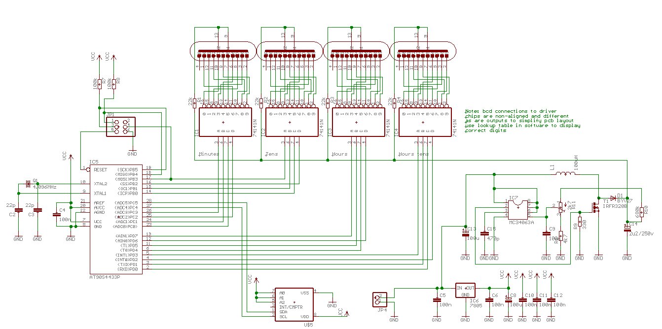
Much tidier - everything except the step-up transformer is on the board now. But three of the decimal drivers have one input mapping, and the other is different. Not as nice as it might be...
Woohoo! It took a couple of goes but I managed to find a route so that all the output chips have the same mapping. But even better news, a complete redesign of the power supply, courtesy of one of the Neonixie group contributors. Now it's a proper switch-mode, controlled by an MC34063A chip and storing energy in a bloody great inductor. There's something about shorting a DC path to ground that offends me, but I guess it will work :) Note that the inductor is somewhat larger than the circuit board layout indicates - it takes up most of the space above IC 3 and IC 4.
Well, it's my own fault. I shouldn't read parts catalogues. But... there's this rather nice little TCN75 chip. You ask it nicely, and it tells you how warm it is. Wouldn't it be nice if this clock could tell the temperature as well as the time? Two wire comms, clock and data, and surface mounted so I can stick it on underneath, or not, just as I please. But how to connect it? I need sixteen pins to output the data to the display, two pins for the setting switches, and two pins to program the chip, and the micro only has eighteen i/o pins.
So...
Can't use any of the output pins - driving the nixies could send signals that will confuse the TCN75. Ditto for the pins listening to the switches, lots of nice bouncing signals there. And hanging it off any of the MOSI/MISO/SCK wires could make it return strange things to the programmer, which would really confuse the issue. Damn.
But wait! I'm not all that keen on the set switches mounting on the board - and I was only going to run cables to the connections anyway. But I'll never need the switches while I'm programming the beastie, so I can use - aha! - the programming connector as a switch connector. The TCN75 now connects where the switches used to be, so now the board is even tidier. Final cut - I've ordered the bits from Farnell's. Time to get the board etched, if I can find a printer that does a good black on cells without burping.
The boards are away for etching - one of my colleagues has kindly offered to do this for me. On the other hand, my components are noticeable by their absence. Time to call Farnells in the morning...
A clock is a very straight forward thing, and even the temperature chip doesn't complicate things too much, for the first iteration.
The crystal is selected to be 4.096MHz. A standard crystal has a stability with temperature of about 50 parts per million and an absolute stability of about 30 ppm - doesn't sound a lot but it adds up to maybe five minutes error a year. For now I'll ignore this - it may be necessary to introduce leap seconds to calibrate the crystal.
The AVRMega CPU has an internal 10-bit prescaler which takes the processor clock and feeds it to timer/counters. It would be convenient to have internal ticks of - say - either one or two milliseconds (the reason for this will become clear when I discuss crossfading the display) so arranging the timer to divide the prescaled clock (250 microseconds) by four will achieve this.
The internal time is kept as hours:minutes:seconds:milliseconds - every time the minutes are incremented, the time is output to the nixie drivers.
Hah! My creation lives! Fetch a brain, Igor...
The circuit boards arrived, and the bits finally made it (a credit card cockup). I started by building the power supplies. Supplies supplies, 5.0v and 180v just where they should be. So I hooked up an anode resistor and a nixie, just for testing, and that worked too. It took a while for the full length of the nixie numeral to light, but only a few minutes. Each nixie was the same, all are happy now. Set the anode current to about a milliamp by measuring the voltage drop across the anode resistor - look for about twenty volts across it, tweaking the variable resistor to set the voltage.
Once I was happy that I could control the voltage (and hence the current
through the nixies) I soldered the rest of the components into the board,
including the nixies. It turns out that the solderpads for the nixie tubes
are a little thin and thus difficult to solder to, but eventually got everything
glued in. The six-way socket is important: it holds the connection to the
computer for programming the microcontroller and the connection to the setting
switches when the clock is running. To connect to the computer, use a 25-way
d-type male wired to a six-way IDC connector as follows
| IDC pin number |
D-type pin number |
| 1 |
11 |
| 2 |
n/c |
| 3 |
5 |
| 4 |
2 |
| 5 |
4 |
| 6 |
18, 19, 20, 21, 22, 23, 24, 25 |
For now, I haven't attached the temperature chip. I don't have enough code space with the free compiler to fit that extra functionality in, so I'm think about other options - maybe using a C compiler or machine code. The code has turned out to be different from what I envisaged last week, too. It turns out that the internal timers on the AVR don't have an automatic preset to count down from (or to count up from) and rather than resetting the count on every interrupt I decided to simply let timer 0 run continuously and trigger an interrupt as it overflows.
The timebase is divided by 256 on the prescaler, so there are 4096000 / (256*256) = 62.5 interrupts per second. I deal with this by making even seconds last 62 interrupts and odd seconds 63 interrupts. The interrupt routine simply counts these interrupts, incrementing the seconds, minutes, and hours counts as necessary. The main loop keeps an eye on the seconds count, and every time it changes it updates the display. It also watches the switches, calling the settime routine when it needs to.
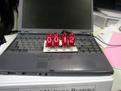
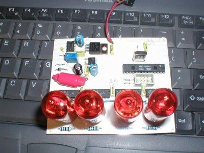
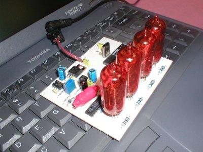
For now, though: Download the code, and three more pics: on the laptop for scale; a view from above, and one from the side. The large red thing is the inductor used in the switchmode power supply generating the 180v. Here's a jpg version of the final schematic, if you don't want to worry about Eagle.